Analysis of Deep Foundations

Deep foundation problems that can be analyzed are, Figure 32:
1- Analysis of an axially and laterally loaded single pile
2- Analysis of laterally loaded single pile by P-y curve
3- Analysis of an axially and laterally loaded single pile
4- Bearing capacity and settlement of single pile or pile wall
5- Analysis of a combined piled raft
6- Stress coefficient according to GEDDES
7- Sheet pile wall
8- Analysis of single barrette
9- Analysis of barrette raft
10- Lateral earth pressure
11- Effective vertical stress
Figure 32 "Deep foundation problems"
The axially and laterally loaded pile can be analyzed by Mindlin solutions. The elastic pile is analyzed using the finite element method, and the soil stiffness is determined from Mindlin analytical solutions. Linear and nonlinear pile analyses can be carried out using hyperbolic functions by defining the limit load. In addition, the pile could be analyzed as a single pile, or a pile connected with (Column/ Foundation). Furthermore, the pile head could be free/ fixed or any other constraint, also the column or foundation edge. Half-space and layered soil models are considered.

The laterally loaded pile can be analyzed by different P-y curves. The elastic pile is analyzed using the finite element method. And the soil reaction is determined from P-y curves. The pile could be analyzed as linear or nonlinear material according to different international design codes. The pile could be analyzed as a single pile, or a pile connected with (Column/ Foundation). The pile head could be free/ fixed or any other constraint, also the column or foundation edge. Half space and layered soil models are considered.
You can define the pile material if the pile is analyzed as linear material. Or you can choose pile section material where the pile can be analyzed as nonlinear material (Elastic circular section, Circular reinforced concrete section, steel pipe, Circular reinforced concrete section with casing, and Circular steel tube section filled with concrete). If the pile section is Circular reinforced concrete section, Circular reinforced concrete section with casing or Circular steel tube section filled with concrete you can choose the design code. The pile can be analyzed using design codes such as ACI 318 (American Concrete Institute), EC2 (Eurocode 2), ECP (Egyptian Code of Practice), IS 456 (Indian Standard 456), BS 8110 (British Standard 8110), CP 65 (Singapore Standard CP 65), CSA A23.3 (Canadian Standard A23.3), HK CP (Hong Kong Code of Practice), and another to choose your factors, so the pile will be analyzed as nonlinear material according to the selected design code (this option will analyze only a single pile without a foundation/column).
You can select the soil model (Soft clay (Matlock), API soft clay, Stiff clay with free water (Reese), Stiff clay without free water (Reese), Modified Stiff clay without free water, Sand (Reese), API sand, Silt cemented C-φ soil, Liquefied sand (Rollins), Loess soil, Weak rock (Reese), Strong rock (Vuggy Limestone)) with/without constant soil parameters at top and bottom soil layer. Also, you can choose to analyze static or cyclic loading. In addition, you can define the initial modulus of the subgrade reaction or let it determine automatically.
You can choose the concrete grade according to the selected design code (ACI 318, EC 2, ECP, IS 456, BS 8110, CP 65, CSA A23.3, and HK CP), where the modulus of elasticity and modulus of the rapture of the concrete, reduction factor for sustained loading, the compressive strain at peak stress and the ultimate compressive strain are determined and taken according to the chosen concrete grade and design code. If you are going to define other parameters, you must choose the "Another" design code. The concrete stress-strain curve can be determined according to three different models: (Parabolic rectangular curve, Hognestad et. al. 1955, or Mander et. al. 1988).

The laterally loaded pile can be analyzed as an elastic embedded pile. The elastic pile is analyzed using the finite element method, and the modulus of the subgrade reaction could be calculated according to Bowels (1997) or by defining the modulus by the user. In addition, the pile could be analyzed as a single pile, or a pile connected with (Column/ Foundation). The pile head could be free/ fixed or any other constraint, also the column or foundation edge. Half-space and layered soil models are considered.

Bearing capacity and settlement of single piles or pile walls according to DIN 4014 can be determined. The input data are dimensions of piles, pile tip resistance from penetration test or cohesion Cu of the layers. Skin friction of the pile can be defined by the user or determined according to DIN 4014, (Figure 36 to Figure 39)
Figure 36 "Bearing capacity and settlement of single pile or pile wall", Pile data
Figure 37 "Bearing capacity and settlement of single pile or pile wall", Skin friction part
Figure 38 "Bearing capacity and settlement of single pile or pile wall", End bearing part
Figure 39 Load settlement curve for pile according to DIN 4014
The settlement of groups of vertically loaded piles and rigid piled rafts on layered soil or half-space medium can be determined, (Figure 40 to Figure 47). The methods of soil analysis are:
  • Linear analysis
  • Nonlinear analysis using a hyperbolic function for load-settlement
  • Nonlinear analysis using German standard DIN 4014 for load-settlement 
  • Nonlinear analysis using German recommendations EA-Piles for load-settlement (lower table values)
  • Nonlinear analysis using German recommendations EA-Piles for load-settlement (upper table values)
Figure 40 "Analysis of piled raft"
Figure 41 "Analysis of piled raft", Pile geometry
Figure 42 "Analysis of piled raft", Pile cap
Figure 43 "Analysis of piled raft", Soil profile
Figure 44 System of loading
Figure 45 Pile location and groups
Figure 46 Contact pressure under the piled raft
Figure 47 Pile reactions of piled raft
Stresses coefficient due to a load under the surface according to GEDDES can be obtained in Figure 48 and Figure 49‎.
Three types of loading are considered:
  •    Stress coefficient for a point load.
  •    Stress coefficient for uniform skin friction.
  •    Stress coefficient for linear variation of skin friction.
Figure 48 "Stress coefficient according to GEDDES"
Figure 49 Stress coefficient according to GEDDES
Sheet pile walls can be categorized into anchored or cantilever types and can be analyzed in three ways: as a cantilever, free earth support, or fixed earth support. The Limit Equilibrium Analysis (LEA) method is used to analyze and determine the sheet pile length while the finite element method is used to determine deformations of the sheet pile.
The Limit Equilibrium Analysis (LEA) method is a commonly used technique for analyzing the stability of sheet piles. This method involves evaluating the forces and moments acting on the sheet pile and determining whether the pile is stable under the given loading conditions. The LEA method considers the forces acting on the sheet pile in both the horizontal and vertical directions. The horizontal forces include the soil pressure and any external loads acting on the structure, while the vertical forces include the weight of the pile and any soil or water above the pile. To perform a LEA analysis for a sheet pile, the following steps are typically followed:
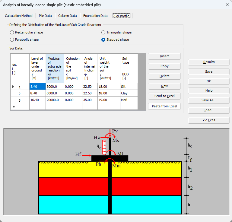
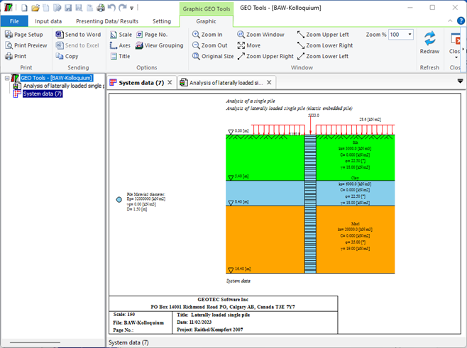
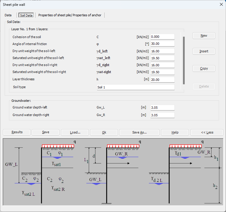
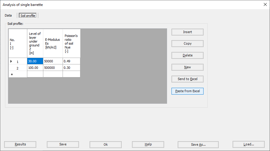
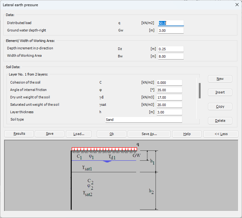
1- Determine the soil properties: The first step in the analysis is to determine the soil properties, including the soil type, strength, and stiffness. This information is used to calculate the soil pressure acting on the sheet pile.
2- Define the loading conditions: The next step is to define the loading conditions, including any external loads and the water level. This information is used to calculate the forces and moments acting on the sheet pile.
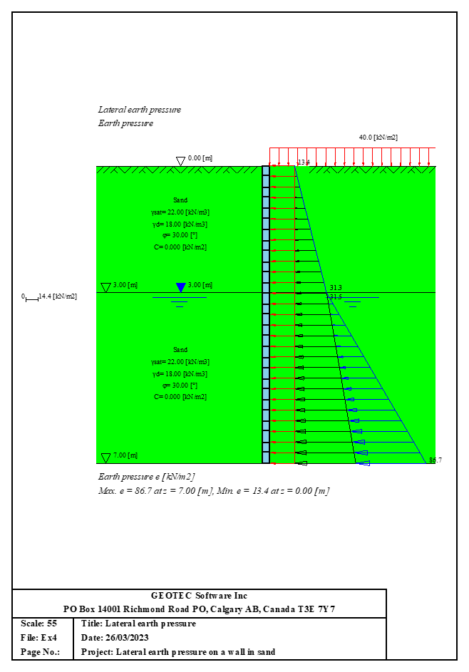
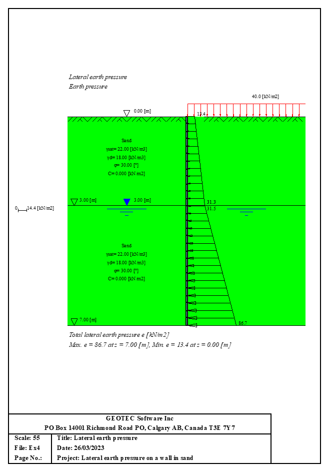
3- Calculate the forces and moments: Using the soil properties and loading conditions, the forces and moments acting on the sheet pile are calculated. This includes the soil pressure, water pressure, and any external loads.
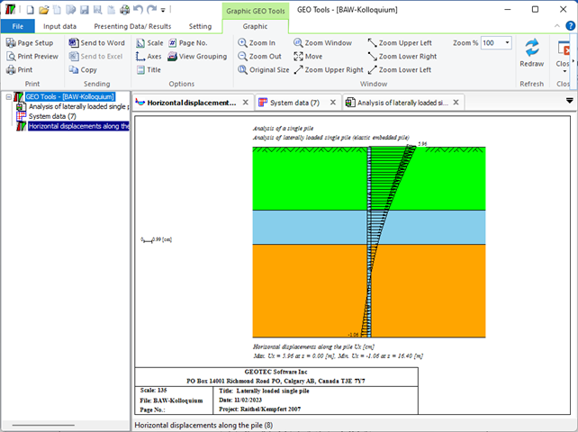
4- Evaluate stability: The final step is to evaluate the stability of the sheet pile. This is done by comparing the forces and moments acting on the pile to its capacity to resist those loads. If the pile is stable, the analysis is complete. If not, modifications to the design may be necessary.
LEA is a widely used method for analyzing the stability of sheet piles, and it can be used to evaluate the performance of different sheet pile configurations and installation methods. However, it is important to note that the results of the analysis are only as accurate as the input data, and careful consideration must be given to the assumptions and limitations of the method.
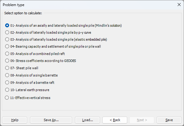
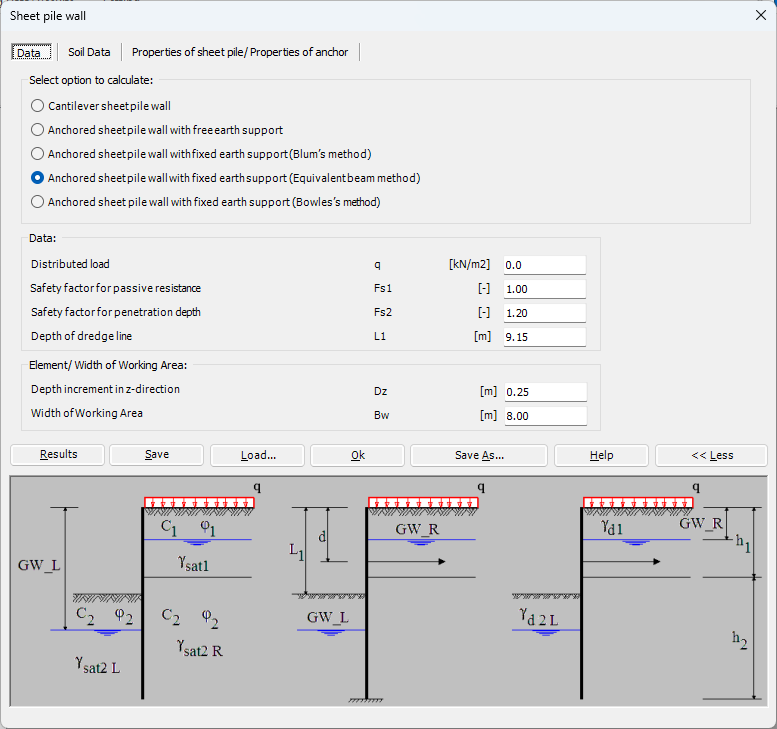
The Limit Equilibrium Analysis (LEA) method is commonly used to determine sheet pile length and stability, considering forces and moments acting on the sheet pile in both horizontal and vertical directions. The analysis involves determining the soil properties, loading conditions, calculating forces and moments, and evaluating stability. However, the accuracy of the results depends on the input data, and assumptions and limitations of the method must be considered. These are different types of sheet pile walls used in the field of geotechnical engineering and construction five of these can be used in GEO Tools:
1- Cantilever sheet pile wall: This is a type of retaining wall made up of interlocking steel, concrete or wood sheet piles that are driven into the ground. The piles are designed to act as cantilevers, resisting the lateral pressure of soil and water on one side, while being supported by the soil on the other side.
2- Anchored sheet pile wall with free earth support: This type of retaining wall is similar to the cantilever sheet pile wall, but it includes additional support in the form of anchors that are installed into the soil behind the wall. The anchors provide additional resistance against the lateral pressure of the soil and water.
3- Anchored sheet pile wall with fixed earth support (Blum's Method): In this type of retaining wall, the sheet piles are anchored to a rigid structural element such as a concrete beam or slab. The structural element acts as a fixed support, preventing the sheet piles from deflecting inward.
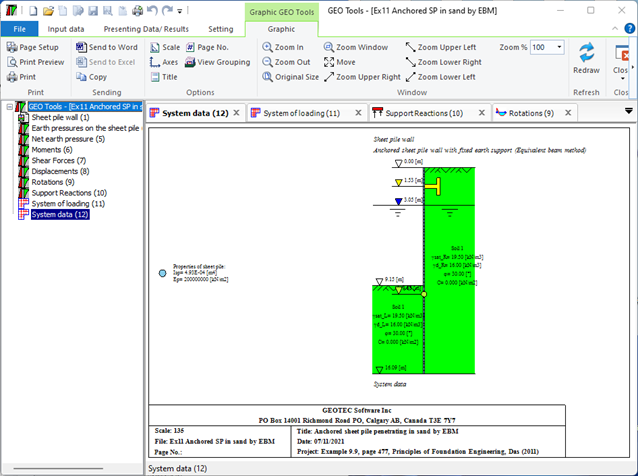
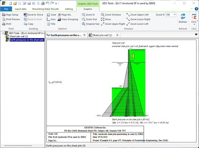
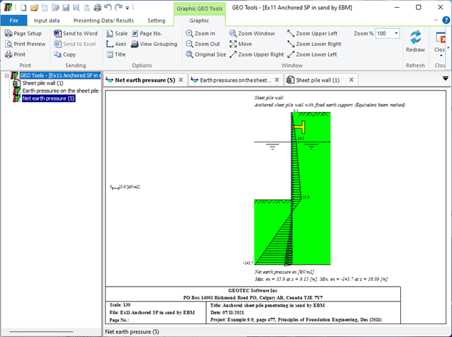
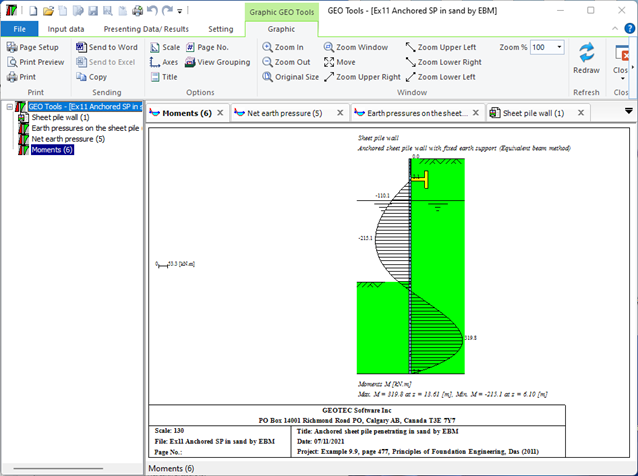
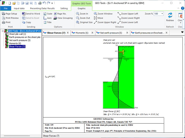
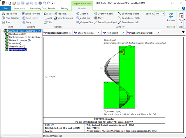
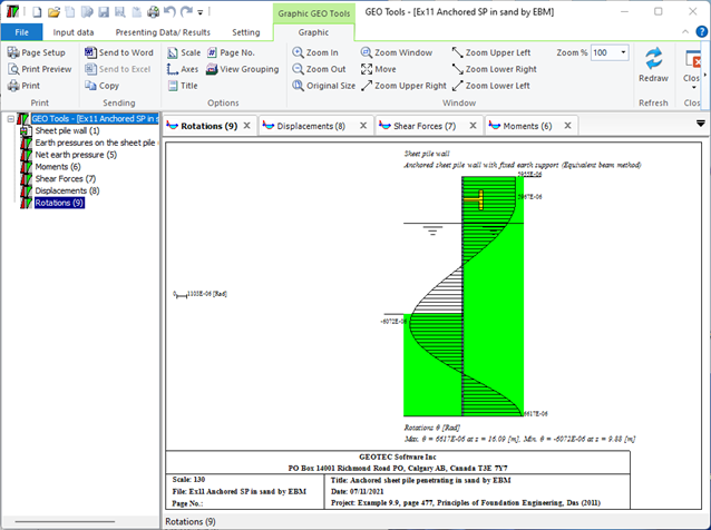
4- Anchored sheet pile wall with fixed earth support (Equivalent beam Method): This method involves treating the sheet pile wall as an equivalent beam and analyzing the forces acting on it. The fixed end of the beam is anchored to a rigid structure, while the free end is supported by the soil. The analysis is used to determine the required size and spacing of the anchors.
5- Anchored sheet pile wall with fixed earth support (Bowels's beam Method): This method is similar to the equivalent beam method, but it also takes into account the soil resistance acting on the sheet pile wall. The analysis involves calculating the bending moment and shear forces acting on the sheet piles and designing the anchor system accordingly.
Linear and nonlinear analyses for barrettes can be carried out. Elastic barrette is analyzed using the finite element method. It is possible to analyze a single barrette under moments and loads in x-, y- and z-directions on layered soil or half-space soil medium, (Figure 55 to Figure 59).
Figure 55 "Analysis of single barrette"
Figure 56 "Analysis of single barrette", Soil profile
Figure 57 Elastic displacement along the barrette
Figure 58 Bending moment along the barrette
Figure 59 Load displacement curve of barrette
The settlement of groups of vertically loaded barrettes and rigid barrette rafts on layered soil or half-space medium can be determined, (Figure 60 to Figure 64). The analysis of barrette groups and barrette rafts can be carried out linearly or nonlinearly according to the following cases:
  1.    Elastic barrette groups
  2.    Rigid free-standing raft
  3.    Rigid barrette raft foundation
  4.    Elastic barrette raft foundation 
Figure 60 "Analysis of barrette raft", Barrette data
Figure 61 "Analysis of barrette raft", Barrette geometry
Figure 62 "Analysis of barrette raft", Soil profile
Figure 63 "Analysis of barrette raft", Barrette cap
Figure 64 Settlements as contour lines

Lateral earth pressure is the pressure that soil exerts in the horizontal direction. Lateral active earth pressure at point A in the soil is equal to the effective vertical stress σ'v multiplied by a coefficient, σh= ka σ'v. If a water table exists, horizontal hydrostatic water pressure is considered. Lateral water pressure at point A in the soil is the weight of the water column above that point w=γwz.

About GEOTEC Software

GEOTEC Software is providing universities and consulting companies with the right tools for the last 25+ years. We also assist our clients in various geostructural projects. From basic to advanced problems, GEOTEC Software can provide you with the right technical assistant.

Language

Select your language

Search

Search